
Recent Updates
Ribo ITP Protocol
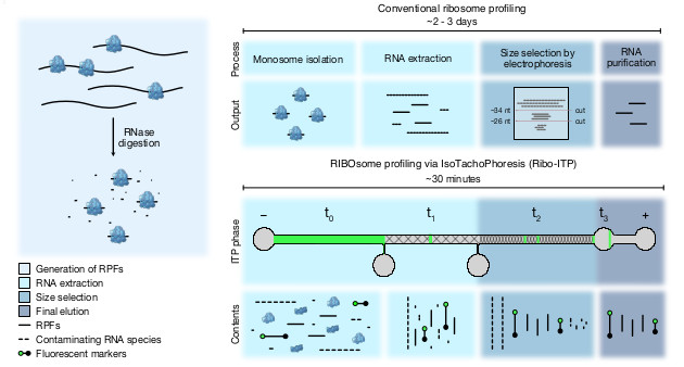
RIBO some profiling via I soT achoP horesis (Ribo-ITP )
Detailed online protocolVersion 1, January 20, 2022
- Overview
- Materials list
- Pre-experimental setup
- Ribo-ITP Protocol
- General Considerations
- Other Considerations
- Overview
- Purpose The purpose of this protocol is to detail the RIBOsome profiling via IsoTachoPhoresis (Ribo-ITP) protocol described in Ozadam et al. 2023 to maximize execution and reproducibility in other laboratories. Here, we detail all reagents and materials needed, steps to take for experimental setup, and the Ribo-ITP protocol, and general considerations. Please also see our recent protocol paper [Rao, Tonn, Cenik].
- Materials list
- Materials A list of materials for Ribo-ITP is available in a spreadsheet here.
- Purchasing molds for microfluidic chips
- Create an account with ProtoLabs.
- Begin a new project and click on "Generate a New Quote".
- Choose the ‘3D Printing’ service and upload the Extended_channel_3D.SLDPRT
- Ensure the following settings are selected from their drop-down menus:
- Material- ABS-Like Translucent Clear (WaterShed)
- Resolution- High Res
- Finish- Unfinished
- Orientation- Custom
- Under the ‘More Options’ setting, include the special instruction to use a Substrate Build. It is important that this setting is clearly defined to ensure smooth and clear molds are made.
- Click ‘Review Quote’ and continue through the purchasing page.
- Pre-experimental setup
- Buffer preparation A printable version of the following table is also provided here.
- Gel purification of fluorescent DNA oligonucleotides
- Place a 10-well 15% TBE Urea Polyacrylamide Gel in the running chamber and fill with 1x TBE Buffer.
- Clean all wells with 1x TBE Buffer and prerun the gel at 200V for 15 minutes.
- While the gel preruns, prepare the gel inputs as follows:
- 19ntfl ddC input: 3ul 100uM 19ntfl ddC DNA + 15 ul NFH2O + 18 ul 2x loading buffer.
- 36ntfl ddC input: 3ul 100uM 36ntfl ddC DNA + 15 ul NFH2O + 18 ul 2x loading buffer.
- Heat the inputs at 80C for 90 seconds.
- Clean the gel wells one final time with 1x TBE Buffer.
- Load 12ul of the prepared marker inputs into the preran 15% TBE Urea Polyacrylamide Gel. There should be 3 wells for each marker.
- Run the gel at 100-115 V.
- The gel is run at a low voltage to ensure good movement. The current should be as close to 0 as possible.
- The run should last > 2 hours
- Cut bands out over blue light source. The method in cutting the band will greatly depend on the bands at the time of the run:
- Smeared bands = cut closer to the top of the band.
- Markers present beneath the bands = cut closer to the top.
- No bands under the gel, but in a nice, sharp line = cut the entire band.
- UV light sources should not be used when cutting.
- Combine the gel slices into 1.5 mL microcentrifuge tubes (3 per tube).
- Spin the tube down using a microcentrifuge.
- Crush the gel with a pestle and clean the pestle when adding 330ul gel extraction buffer.
- Incubate the markers for 30 min on dry ice.
- Incubate overnight covered in foil at room temperature on table top shaker or on the HulaShaker.
- Spin down the marker slurry with a microcentrifuge.
- Cut the tip off a low retention, DNAse and RNase free 1000 uL pipette tip with cleaned scissors and transfer all slurry to 0.22um spin filter tube.
- Spin the filtered tube for 1.5 min at 13,000x G using a table top centrifuge.
- Transfer the elution to a non-low bind 1.5 ml tube.
- Bring volumes to 330 ul with gel extraction buffer.
- To each tube, add 1.5ul glyco blue and 1 mL of cold 100% Ethanol. Cf = 300mM sodium acetate, 75% Ethanol
- Allow for overnight precipitation in -20C. Note that Longer precipitation times ensure greater yield.
- Spin the precipitated markers for 1 hour at 20,000x g with a table top centrifuge set at 4C.
- Carefully remove the supernatant without disrupting the pellet.
- Spin the markers a couple of times to remove any excess ethanol.
- Allow the pellets to dry by storing them sideways to prevent contaminants from entering the tube. Note: do not let the pellets overdry! This is characterized by its translucent color.
- Resuspend the pellets in 15 uL of nuclease free water and let sit for 10-15 minutes, or until the pellet has completely dissolved in the water.
- Transfer the 15 uL of resuspended markers into a DNA Low-Bind 1.5 mL microcentrifuge tube. If there are multiple tubes for a single marker, combine the resuspended pellets into the same tube.
- Bring the final volumes up to 50 uL .
- Heat for 2 minutes at 70 C, then immediately move to ice.
- Check concentrations on nanodrop: Example concentrations are 19ntfl ddC DNA 41.9ng/ul; A260/A280: 1.56; A260/A230: 1.27 and 36ntfl ddC DNA 73.1ng/ul; A260/A280: 1.56; A260/A230: 1.27.
- Prepare 5uM stocks of the markers based on their nanodrop concentrations and molecular weights provided by the manufacturer.
- Check again on nanodrop and calculate the final molarity.
- Aliquot the markers into DNA Low-Bind tubes to avoid the freeze-thaw cycle.
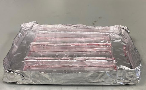
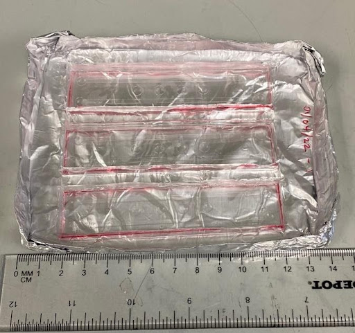
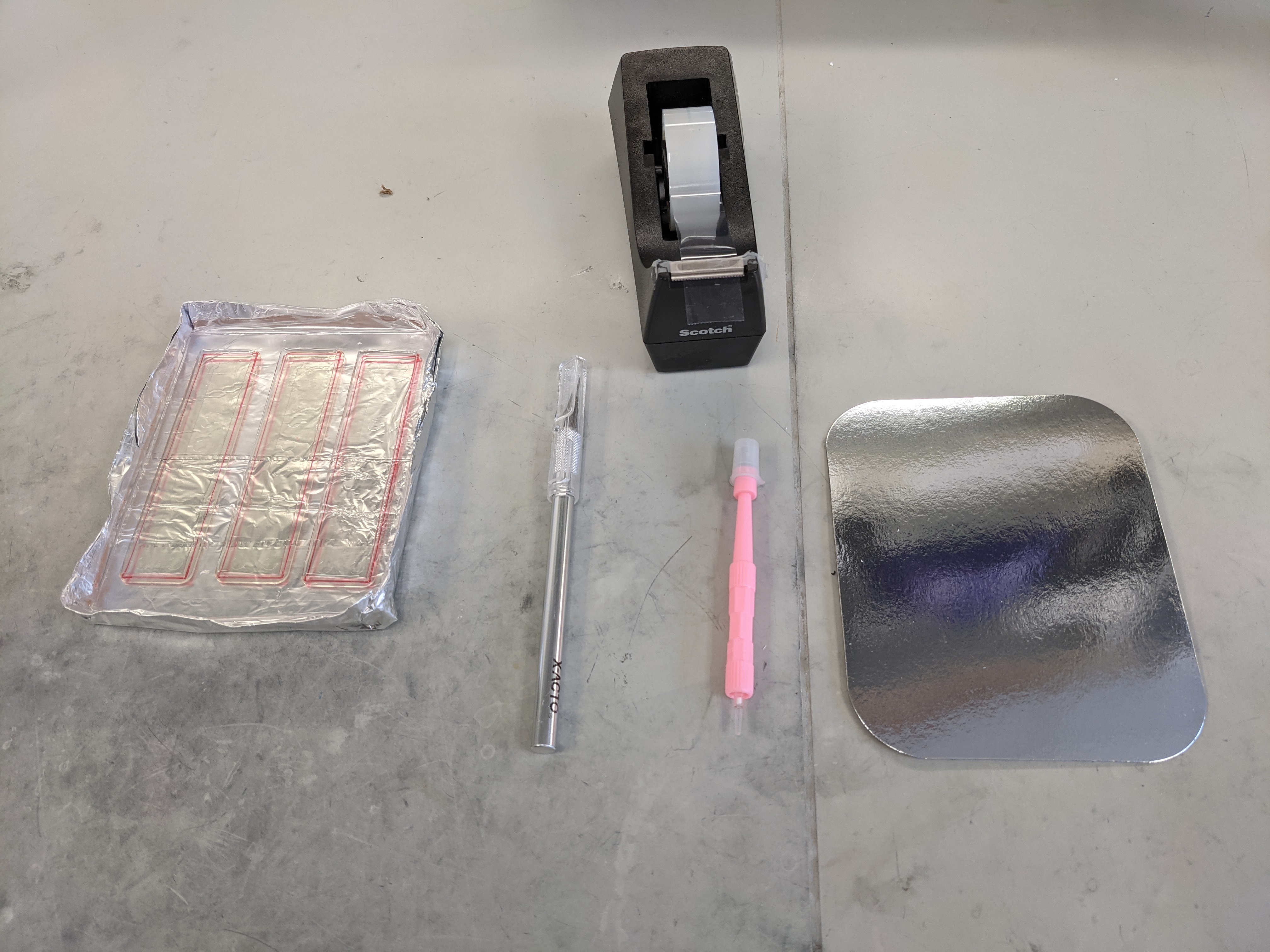
- Mold setup for Ribo-ITP chips
- Create a mold tray by folding a sheet of aluminum foil into (LxWxH) 10cm x 13.5 cm x 3 cm
- Using a permanent marker, line the outer edge of the ITP chip mold to guide where the chip will be cut and removed.
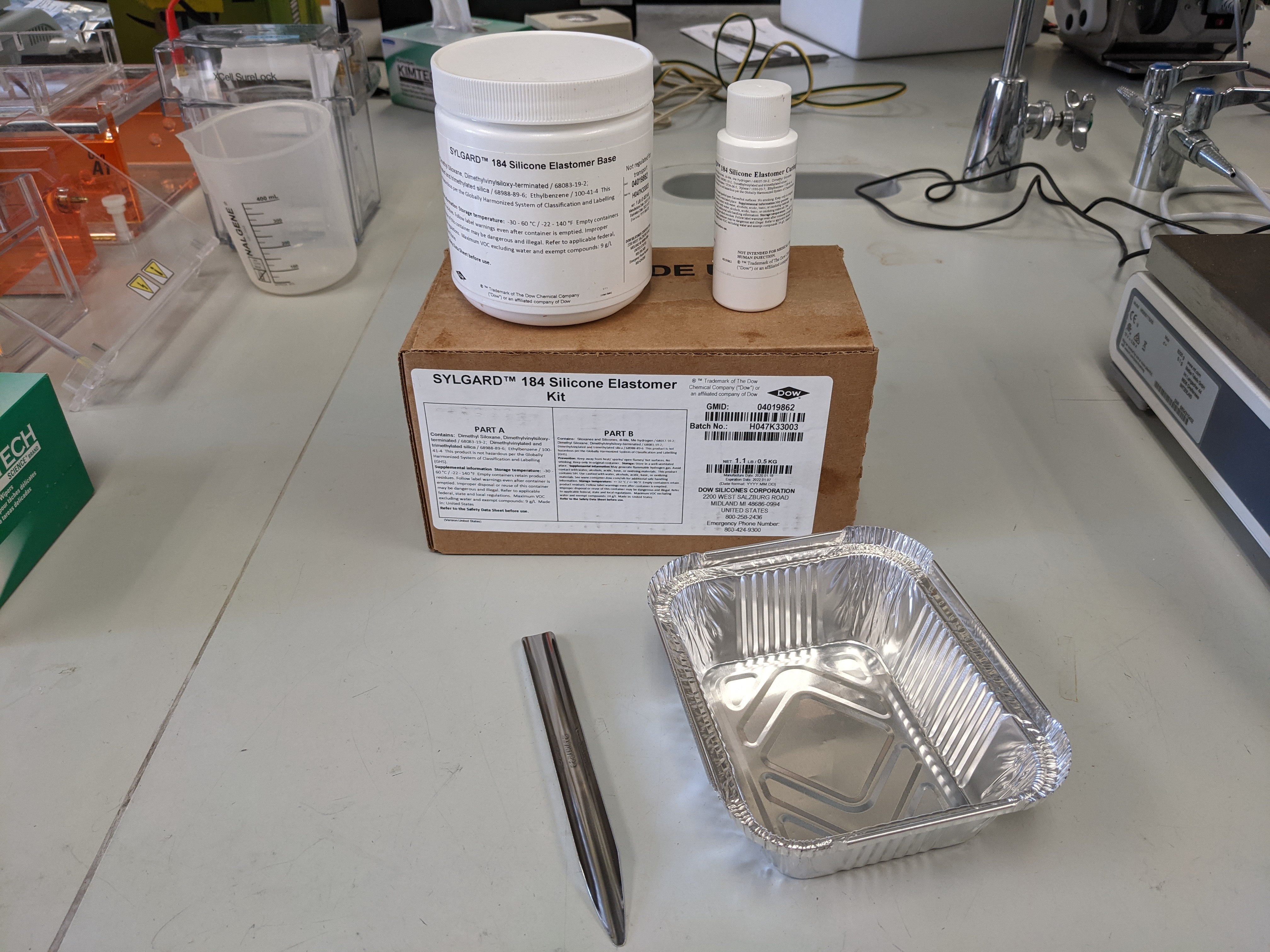
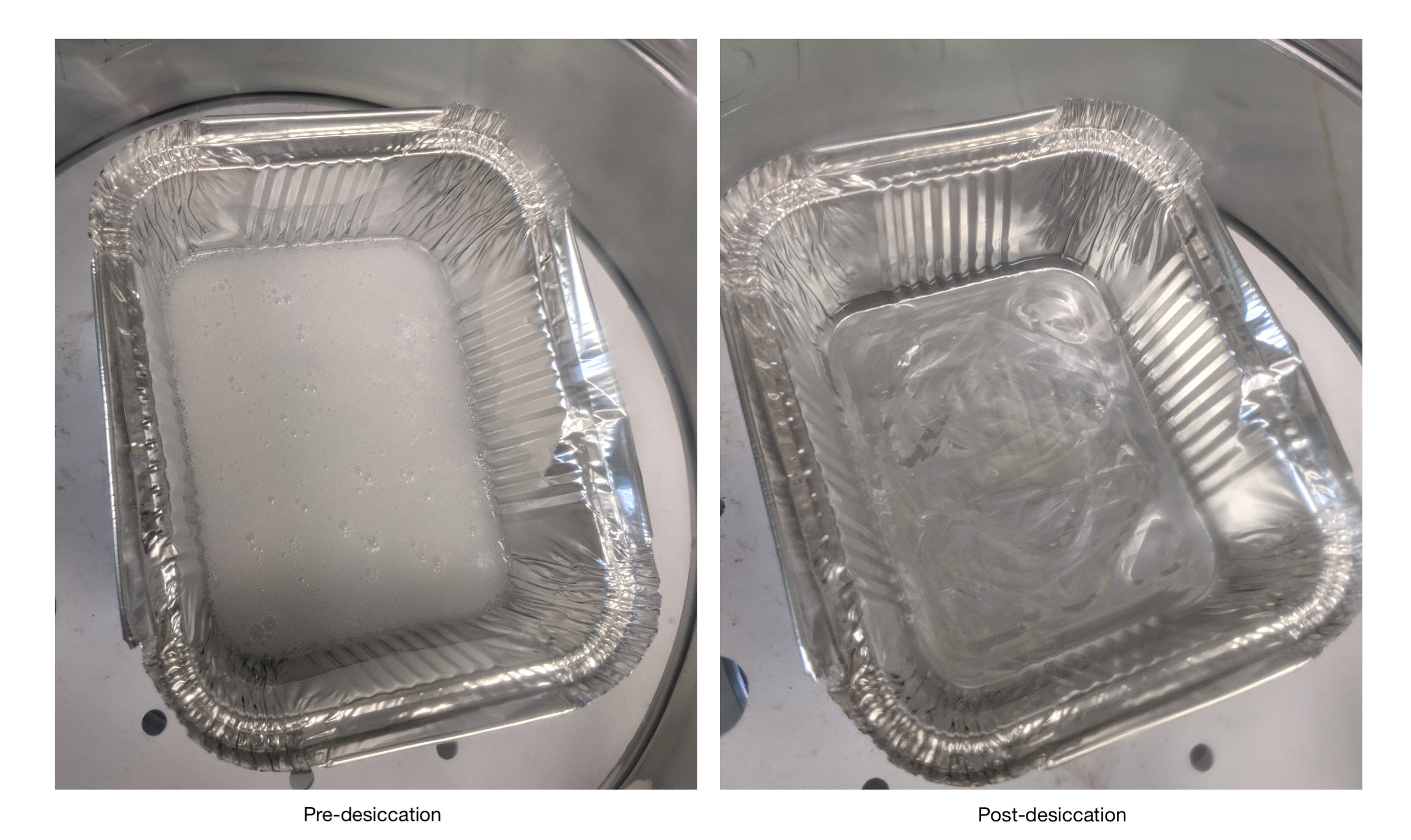
- Pour out 100g of the PDMS monomer and 10g of the curing agent and desiccate the mixture as outlined in the Manufacturing Ribo-ITP chips section.
- Once the desiccation is complete, align three ITP chip molds in the aluminum foil tray and pour the entirety of the mixture on top.
- Ensure the molds lie flat at the bottom of the tray with no bubbles present underneath. Gently press on the molds to squeeze out any air bubbles
- Desiccate the mixture until all the bubbles have been removed.
- Incubate at 50C overnight or until the PDMS is no longer sticky.
- Remove the chips according to the Manufacturing Ribo-ITP chips section.
- Manufacturing Ribo-ITP chips
- Mix Sylgard 184 PDMS monomer and curing agent (Ellsworth) at 10:1 (w/w) ratio.
- For initial setup of the molds, the PDMS mixture should be of sufficient volume to cover the entire mold (i.e. to cover the glass slide and the attached molds) and reach a depth of at least ~2 cm.
- For subsequent experiments after the initial setup, prepare enough of the PDMS mixture to provide ~7 g of PDMS mixture to each two-lane mold.
- Degas the PDMS mixture in a desiccator connected to a vacuum chamber for ~30 min or until no visible air bubbles are seen.
- Pour the degassed PDMS mixture evenly onto the molds.
- For initial setup of the molds, pour the PDMS mixture over the entire surface of the mold (i.e. to cover the glass slide and the attached molds) and reach a depth of at least ~ 2 cm.
- For subsequent experiments after the initial setup, pour the PDMS mixture evenly over the exposed surfaces of the chips, ensuring that each gets approximately 7 g of PDMS mixture and reaches a depth of at least ~2 cm.
- Degas the PDMS mixture in a desiccator connected to a vacuum chamber for ~30 min or until no visible air bubbles are seen.
- Incubate the PDMS molds at 50°C overnight.
- After overnight incubation, remove the molds from the incubator and touch the top of the molds with gloved fingers to ensure that the PDMS has solidified and is no longer sticky. If any stickiness or liquid PDMS is noted, return the molds to the 50°C incubator until curing is complete.
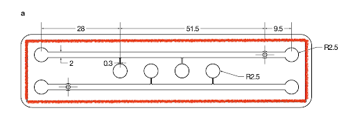
- Using a razor blade, cut the PDMS slabs from the molds along the border of the chips.
- The border is indicated by red below.
- Take care to avoid cutting the molds and PDMS slabs in the areas of the channels to maintain their integrity
- 3 PDMS slabs (6 lanes total) fit on a 5” x 4” glass slide.
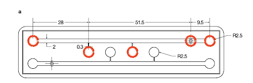
- Place the PDMS slabs feature-side up and punch out the five reservoirs using a 5 mm diameter biopsy punch.
- The borders of the reservoirs are indicated by red circles below.
- Cover channels with tape for storage, or continue to plasma cleaning.
- Plasma clean the PDMS slabs and glass slide as follows:
Important note: The plasma cleaning protocol may need to be optimized for different plasma cleaner setups. - Turn on power of plasma cleaner and vacuum gauge.
- Place PDMS channel feature side up and glass slide (4’’ by 3’’; Ted Pella) in chamber (pre-clean the slide and channel with tape).
- Make sure the 3-way valve is closed (lever pointing down).
- While holding the door shut, turn on the vacuum pump.
- Let the vacuum pump down to 0.25 Torr (can take up to 15 min).
- Open the 3-way valve to let air flow (lever pointing left). Let the pressure again reach 0.25 Torr.
- Turn on the RF power to “HI” and treat the samples for 2 min. Bright violet plasma color should be observed.
- Turn off the RF and vacuum pump, and close the 3-way valve (lever pointing down).
- Slowly vent the chamber by opening the 3-way valve slightly (lever pointing slightly to the right).
- Should hear a hissing sound as the air evacuates. This should be done slowly (takes at least 1 min).
- Chamber is fully vented when pressure returns to atmospheric pressure
- Open the chamber and bring the plasma-treated surfaces together. You can gently push air bubbles from beneath the PDMS, but it is not necessary to push hard, as this can damage the channels.
- Heat the chips at 80°C for a minimum of 15 minutes and up to overnight to enhance bonding.
- Cover channels with tape for storage.
- Ribo-ITP protocol
- Cell preparation: dilution method for cell culture *Use this method if performing Ribo-ITP with dilutions of K562 cells
- Grow K562 cells in RPMI 1640 + 10% FBS (media).
- Pellet cells at 300 g for 10 min.
- Resuspend cells with 5 mL media.
- Wash cells once with 1x phosphate buffered saline (PBS) then resuspend in 1 ml PBS.
- Pellet cells in PBS at 300 g for 10 min.
- Remove PBS and resuspend pellet in Lysis Buffer Working Solution to get desired cell concentration in a final volume of 5 μL. We used a dilution equivalent to 100 cells in 5 μL of buffer.
- To generate ribosome protected fragments, proceed to the section titled “Nuclease digestion for generation of ribosome protected fragments (RPFs) from diluted cell culture lysate”.
- Fluorescence-Activated Cell Sorting (FACS) for cell culture *use this method if performing Ribo-ITP with sorted K562 cells
- Grow K562 cells in media containing RPMI 1640, 10% FBS, 2 mM Glutamine (Gibco) and penicillin/streptomycin (Sigma).
- Pellet the cells at 300g for 5 minutes.
- Wash once with 1x PBS and resuspend in ~1x10 6 cells/mL of PBS.
- Pass the cells through a strainer cap to achieve a single cell suspension.
- Prepare a LoBind Eppendorf 96-well PCR plate for cell sorting by adding 5 uL of Lysis Buffer Working Solution to required wells.
- Seal the plate with a PCR plate adhesive and spin the plate down in a table top centrifuge set at 4C for 5 minutes at 300g. Spin for an additional 5 minutes if bubbles remain.
- Keep the plates on ice until FACS.
- Move the 96-well prepared PCR plate to the front right corner of the FACS machine plate holder.
- Define single cells by gating with FSC-A/SSCA, SSA-H/SSW, FSCA/FSCH and FSCA- histogram for bigger cells and follow with cell sorting.
- Seal the plate with a PCR plate adhesive seal and immediately dip in liquid nitrogen.
- Move plates for immediate processing onto ice. Store plates to be processed at a later time in - 80C.
- To generate ribosome protected fragments, proceed to the section titled “Nuclease digestion for generation of ribosome protected fragments (RPFs) from sorted cells”.
- Preparation of mouse oocytes and embryos. *Use this method if performing Ribo-ITP with mouse oocytes or embryos.
- We refer to the methods section of our manuscript, Single cell quantification of ribosome occupancy in early mouse development, for Mouse oocyte isolation and In vitro fertilization (IVF) using CAST/EiJ sperm
- GV and MII collected from C57BL/6J mice (female).
- IVF performed in order to get 1, 2, 4 and 8-cell stage embryos (CAST/EiJ (male) x C57BL/6J).
- Oocyte collection performed as done by Borensztein et al in Transcriptome Profiling of Single Mouse Oocytes (2018)
- This collection method minimizes the final buffer volume in the starting sample (<1 μL each).
- Upon collection, samples are added to low bind 0.2 ml PCR tubes (Axygen) and submerged in liquid nitrogen. Samples are immediately transferred to -80°C for storage until sample processing, which takes place as soon as possible. We have found that the sooner the samples are processed after collection, the better our data. For the mouse samples in the ITP paper, samples were processed within 24 – 48 of collection.
- To generate ribosome protected fragments, proceed to the section titled “Nuclease digestion for generation of ribosome protected fragments (RPFs) from mouse oocytes, embryos” section.
- PDMS chip preparation for Ribo-ITP experiments
- Prepare prepolymer mixes (10% and 5% PPM) according to the recipes in the “buffers” section. Heating at 50°C and vortexing the prepolymer mix is necessary to fully dissolve the urea. Vortex again after addition of VA-086, and cover tubes with foil to reduce light exposure.
- Attach PDMS chip to blue light source with tape.
- Pretreat the channels of the ITP chip by filling the entire chip with each solution for the indicated amount of time. Empty and dry the channels between each step using a Pasteur pipette tip attached to a vacuum hose and liquid trap.
- 1 min of RNaseZap (100% concentrate).
- Nuclease-free water rinse.
- 1 min of 1 M NaOH.
- Nuclease-free water rinse.
- 10 min of 10% (w/v) Benzophenone in Acetone.
- During benzophenone treatment, prepolymer mixes heated at 50°C for 10 min.
- Ensure there are no bubbles present during the treatment; more of the solution can be pipetted into the channel during treatment to remove bubbles.
- 1 min of MeOH.
- 1 min of 0.1% Triton X-100 in nuclease-free water.
- Polyacrylamide stacking
- Secure chip to UV light source (turned off) with tape to avoid disturbing the prepolymer mix prior to polymerization.
- Fill the 10% polyacrylamide channel with the 10% PPM by dial pipetting into the size-selection/10% PA channel through the elution well.
- Dial pipetting was performed by slowly turning the volume knob to the left to reduce the displayed volume in the micropipette.
- Ensure that the prepolymer mixtures are being pipetted into the channel by aligning the pipette tip right at the channel entrance.
- Take extra care to ensure the 10% PPM does not block branch channel 2 when loading.
- Fill the extraction channel/5% polyacrylamide channel with the 5% PPM by dial pipetting through branch channel 2. Ensure the 5% PPM does not block branch channel 1 when loading as this will not prevent the loading of the lysate into the lysate channel.
- Expose chip containing the stacked PPM to UV light for one minute, followed by darkness for 30 seconds
- Repeat UV exposure two more times for a total three-minute exposure.
- Fill all empty channels and reservoirs with LE storage buffer to avoid polyacrylamide dehydration.
- While waiting to perform ITP, cover the chips with a box or foil to protect from light. Chips are typically used within 30 min to 6 hours of preparation.
- Nuclease digestion for generation of ribosome protected fragments (RPFs) from diluted cell culture lysate. * Digestion should be timed so that the incubation step ends right before loading it into the lysate channel
- Dilute MNase stock [2000 U/μL] (NEB). Dilute 1:50 in lysis buffer for 100 cell dilution experiments by adding 2 μl MNase stock to 98 μl lysis buffer.
- Add 1 μl of the diluted MNase to the lysate, cap the PCR tube, and incubate in thermal cycler for 30 min at 37°C.
- Dilute EGTA to 70 mM in lysis buffer and keep on ice.
- Add 1 μl of EGTA [70 mM] solution to the lysate to a final concentration of 10 mM.
- If working with tubes, vortex samples and spin down.
- If working with plates, pipette to mix.
- Keep lysate on ice until Ribo-ITP.
- Nuclease digestion for generation of ribosome protected fragments (RPFs) from sorted cells Digestion should be timed so that the incubation step ends right before loading it into the lysate channel.
- Dilute MNase stock [2000 U/μL] (NEB). Dilute 1:150 in lysis buffer for sorted single cell experiments by adding 2 μl MNase stock to 298 μl lysis buffer.
- Add 1 μl of the diluted MNase to the lysate, seal the PCR plate with a PCR plate adhesive.
- Spin the plate down in a table top centrifuge set at 4C for 2 minutes at 2,000g.
- Immediately incubate the digestion reaction at 37C for 28 minutes.
- Dilute EGTA to 70 mM in lysis buffer and keep on ice.
- Add 1 μl of EGTA [70 mM] solution to the lysate to a final concentration of 10 mM and pipette to mix.
- Keep lysate on ice until Ribo-ITP.
- Nuclease digestion for generation of ribosome protected fragments (RPFs) from mouse oocytes, embryos.
- Add 6 μl of Lysis Buffer Working Solution directly to the frozen droplet and place it on a cold block on ice.
- Dilute 2 μl of MNase in 98 μl Lysis Buffer to get the 1:50 dilution. A digestion mix was made by adding 4 μl of the 1:50 MNase to 20 μl Lysis Buffer.
- Repeat until all samples have Lysis Buffer. Pipette up and down ~5x to mix and then briefly centrifuge.
- Samples are immediately digested at 37°C for 30 min.
- After digestion, samples are immediately moved to ice and 1μL of EGTA [70 mM] is added for a final concentration of 10 mM.
- Samples are vortexed and spun down, then kept on ice until ITP.
- Chip setup * Keep pluronic solutions (LEp and TEp) and frozen pipette tips on ice to prevent premature gelling.
- Move chip to blue light source for ITP and secure with tape.
- Remove LE storage buffer from channels immediately prior to use using a Pasteur pipette attached to a vacuum hose and liquid trap.
- Pipet 80 μL LEp through LE reservoir 3 with frozen tips so that it fills both LE reservoir 3 and the channel connecting it to the elution well. Frozen tips are required to prevent LEp from turning to gel early.
- Add 30 μL LEp to LE reservoir 2 using frozen tips, ensuring contact with the polyacrylamide present in branch channel 2.
- Pipet 20 μL running buffer into elution well.
- Add 3 μL of fluorescent DNA markers to the digested lysate (7 μL). Prepare a 1:1 mastermix of gel-purified 19ntfl DNA and 35ntfl DNA [1 μM] in advance, aliquot, and store at -80°C.
- Remove SDB from 50°C heatblock and add 11μL to the sample, then vortex and spin down.
- Load 21 μL volume of the sample mixture was loaded into the lysate channel through branch channel 1 via dial-pipetting.
- Take care to avoid bubbles Take care to avoid bubbles.
- A small amount of the lysate usually spills over into the TE reservoir. Similarly, once the lysate channel is full, it is ok to load a little excess volume directly into the TE reservoir, near the lysate channel.
- Add 30 μL LEp to LE reservoir 1 using frozen tips, ensuring contact with the lysate present in branch channel 1.
- Fill the TE reservoir with 70 μL TEp using frozen pipet tips. Care was taken to avoid bubbles near the lysate channel and to ensure good contact with lysate.
- Place the negative electrode into the TE reservoir and secure it with tape.
- Place the positive electrode into LE reservoir 3 and secure it with tape. Take care to maximize distance between electrodes and LEp or TEp, in order to prevent drying of the pluronic solutions.
- RIBOsome profiling via IsoTachoPhoresis (Ribo-ITP)
- Cover the BlueLight source (Clare Chemical Dark Reader Transilluminator) with its light filter then turn it on to enable fluorophore visualization. Turn off lights in order to visualize fluorophore well.
- A Keithley 2410 Sourcemeter, controlled using MatLab was used to apply a constant 300 uA across the channel with a maximum voltage of 1.1 kV.
- Apply current to the channel to start sample migration.
- When the fluorescent band passes by Branch Channel 1, a secondary negative lead was added to LE Reservoir 1.
- In a typical run, the starting voltage was ~250 V. The voltage initially decreases then increases as resistance in the channel becomes greater.
- In an ideal run, we expect the marker DNAs to concentrate as a sharp band in the 5% PA gel. Upon entering the 10% PA gel, two bands (representative of each DNA marker) are expected to form.
- Watch out for the timing of t/he DNA concentration. We expect the DNA to reach the 5% PA boundary by ~10 min. At the 13–14-minute mark, it should reach the 10% interface. Around 17 minutes, the first marker should be nearing the elution well. After cleaning well and exchanging the collection buffer for Diagenode Dephosphorylation Buffer (DB), sample elution is expected to take ~2 min. A typical run should take ~20-25 minutes.
- A good run will have minimal curvature of the DNA bands, and the two bands should separate more as they travel through the 10% PA gel.
- Pause current application when the lower fl-DNA marker (19ntfl) begins entering the elution well.
- Discard the running buffer and wash the elution well twice with 30 μL nuclease-free water. Avoid leaving residual volume in the well.
- Add 10 μL of 8:2 diluted Dephosphorylation Buffer (DB) (Diagenode) to the elution well. This is equivalent to 8 μL NFH2O + 2 μL DB, which is the starting buffer in the Diagenode D-Plex kit for library prep.
- Resume the current until the upper fl-DNA marker (36ntfl) begins entering the elution well.
- Pipet the 10 μL sample pipetted into a 0.2 ml low bind PCR tube and immediately freeze it at -80C until further processing.
- Library preparation for Ribo-ITP libraries
- Sequencing libraries were prepared using the Diagenode D-Plex Small RNA-seq kit (Diagenode) per manufacturer’s instructions, with the following minor modifications:
- In the dephosphorylation rxn:
- used 1μL of a 1:1 mix of Dephosphorylation Reagent (DR) (Diagenode) and T4 PNK (NEB) instead of just 0.5 μL of DR.
- incubated the samples for 25 minutes at 37C instead of 15 min.
- For low input ITP samples, the RTPM was used as reverse transcription primer (not the RTPH). RTPH is used when we create “bulk” ribosome profiling libraries, with 25ng inputs as starting material.
- For low input ITP samples, a 1:2 dilution of the template switching oligo was required.
- After cDNA synthesis, ½ of the cDNA (13 μL) was stored as backup (-20C or long-term at -80C). The removed 13 μL was replaced with NFH2O and PCR proceeded as written.
- 17 PCR cycles were used for low-input ITP samples (using ½ of the cDNA) in both the SI (single index) and UDI (unique dual index) modules of the kit.
- 1 μL of a 1:4 dilution of the PCR product was assessed via High Sensitivity DNA bioanalyzer.
- A peak of ~200bp is expected when using the UDI module (~30nt inserts).
- A peak of ~190bp is expected when using the SI module (~30nt inserts).
- The sample peak of interest was quantified by bioanalyzer.
- Samples are pooled such that an equimolar amount of the peak-of-interest was present in the pool. 40 μL of the least-concentrated sample is used. It is ok to skip pooling of the samples when dealing with low sample numbers. However, when many samples are being processed, it is helpful to pool “like samples” before bead purification and size selection. (e.g. make a pool of all GV samples, one pool of all MII samples, etc).
- Pools of PCR products were cleaned with Ampure XP beads (1.8x ratio) and eluted in 30 μL NFH2O.
- The entire elution was size selected on a 3% agarose cassette using the Blue Pippin system, targeting either 190 or 200 bp using “tight” settings.
- The 40 μL elution was collected from blue pippin and analyzed using High Sensitivity DNA bioanalyzer. Dilution is usually not necessary for this pool, but think about your expected concentration, which depends on your original sample pool. If needed, samples can be diluted prior to checking on bioanalyzer.
- General considerations
- Working with RNA
- Thoroughly clean your bench, pipets, etc with RNase zap before starting ITP.
- Aliquot stocks of reagents in order to avoid risks of RNase contamination.
- Change gloves often.
- Always use sterile, nuclease free, filtered pipet tips with low retention.
- Preparing PDMS chips
- Some things to look out for if your PDMS chips aren’t working:
- If the liquid PDMS is underbaked after pouring it on the molds, it will be sticky and not bind to the glass channel properly after plasma cleaning. Ensure that the molds are not sticky after overnight incubation at 50C.
- If the edges of the channels are not properly binding to the glass after plasma cleaning, it may be time to prepare new molds. Older molds (~ 1 year old) start consistently having this problem, and replacing them with new ones immediately fixes the problem.
- Fluorescent markers
- This protocol originally used fluorescently labeled RNA markers with 3’ ddC modifications. Despite the ddC blocking nucleotide, RNA markers consistently generated sequencing libraries (i.e negative controls just containing markers and no cellular input generated libraries; upon sequencing, these were clearly our markers). Over multiple tries, fresh RNA markers were re-ordered, single use aliquots were made, resuspension buffers were changed, etc… Due to these issues, the switch to ssDNA markers was made.
- The switch to fluorescently labeled DNA markers with 3’ ddC modifications was made in Jan. 2020. The library prep kit (Diagenode D-Plex) was able to amplify ssDNAs with 3’ OH groups, but not the fl-DNAs with 3’ ddC (after they were gel purified in-lab). Again, since the synthesis companies aren’t able to guarantee 100% purity, it was required to gel purify the markers in house in order to gain higher purity (oligos with lengths n-1 or n-2 are the most common contaminants, which means the most common contaminants lack the 3’ ddC). When gel purifying, only the top ½ of the fluorescent band was extracted to remove ddC-lacking species in stock solutions.
- Nucleases & nuclease inhibition
- Aliquot single-use vials of MNase to avoid freeze thaw cycles.
- It would be great to enhance flexibility in the future by figuring out how to get ITP to work with different nucleases. Since MNase relies on Ca++ for function, EGTA (calcium quencher) served as an effective MNase inhibitor, and only minorly effected size selection/yield at Cf=10mM in ITP. Other nucleases, however, would need different inhibitors.
- We found that VRC migrated just ahead of our RPFs and was present in our collection fractions. VRC is known to inhibit downstream enzymatic reactions.
- We tested proteinase K and found that it altered the digestion profile of our RNA samples. We think that it begins digesting the ribosome prior to fully inhibiting the nuclease, resulting in changes to the RNA profile (overdigestion).
- Test experiments for beginners
- Yield & size selection
- One can run an RNA of choice (small RNA ladder or pre-digested/extracted RNA containing RPFs) through ITP and compare check yield on a gel, as compared to the input RNA. Can also assess size selection (exclusion of unwanted small/large fragments; yield of target fragments).
- Ribosome profiling of ~100 K562 cells
- The first attempt with actual cells should be the 100 K562 cells (dilution method described in protocol).
- Optimizations for new cell types/counts would likely be necessary.
- Other considerations
- pH is very important in ITP.
- Buffers have been optimized to have pH around 7.2. If the pH of buffers is incorrect, check the pH of the BisTris-HCl Master Mix and ensure it is at 7.2.
- If size selection is poor or ITP seems to be running poorly, check the pH of your solutions; especially the lab-made ones.
- Aliquots are your best friend. They help avoid RNase contamination, freeze thaw cycling, etc.
- Our protocol uses 1.5 μL of each 1μM fl-DNA marker. This can be hard to see, but we use this small amount in order to minimize risk of converting these to libraries. Marker amount can be scaled up depending on application.
| Buffer | Section | Final Concentration | Preparation |
|---|---|---|---|
| Gel Extraction Buffer | DNA Marker Purification | 300 mM Sodium Acetate, 1 mM EDTA, 0.25% SDS, pH 5.2 | 3M Sodium Acetate, pH 5.2- 300 uL, 500 mM EDTA- 6 uL, 20% SDS- 37.5 uL, NF-H2O- 2,656.5 uL |
| BisTris-HCl Master Mix | Buffer Preparation | 2.35M BisTris and 361mM HCl in a solution | 2.5M BisTris- 4940 uL, 6M HCl- 316.35 uL |
| 1M BisTris titrated to 7.2 | Buffer Preparation | 1M BisTris and 220mM HCl | BisTris- 10.462 g, NF-H2O- 30 mL, 6M HCl- 1820 uL, NF-H2O- To final volume of 50 mL, |
| Lysis Buffer Working Solution | Buffer Preparation | 20 mM Bis-Tris, 1.0% Triton-X 100, 5 mM MgCl2, 5 mM CaCl2, 100 mM NaCl, 1 mM DTT, 0.1 mg/mL cycloheximide | Add 989 µL Lysis Buffer Stock, 10 µL DTT [100 mM], and 1 µL cycloheximide [100 mg/mL]. Keep on ice. |
| Lysis Buffer Stock | Sample Preparation | 20 mM BisTris, 1% Triton X-100, 5 mM MgCl2, 5 mM MgCl2, 100 mM NaCl, 4.4 mM HCl | 1M BisTris titrated to 7.2- 600 uL, 5 mM CaCl2- 150 uL, 10% Triton x-100- 3 mL, 1M MgCl2- 150 uL, 5M NaCl- 600 uL, NFH2O- 25.5 mL |
| Storage Buffer | Chip Preparation | 130 mM BisTris, 20 mM HCl, 0.5% PVP | BisTris HCl Master Mix- 55.33 uL, 10% PVP- 50 uL, NFH2O- 894.7 uL |
| 10% Polyacrylamide | Chip Preparation | 10% polyacrylamide, 130 mM BisTris, 8M urea, 0.5% VA-086, 20 mM HCl | Urea- 0.4806 g, VA-086- 0.0050 g, 40% acrylamide/bisacrylamide- 250 uL, BisTris HCl Mastermix- 55.33 uL, NFH2O- ~306.6 uL |
| 5% Polyacrylamide | Chip Preparation | 5% polyacrylamide, 130 mM BisTris, 8M urea, 0.5% VA-086, 20 mM HCl | Urea- 0.4806 g, VA-086- 0.0050 g, 40% acrylamide/bisacrylamide- 125 uL, BisTris HCl Mastermix- 55.33 uL, NFH2O- ~432 uL |
| Reservoir LE Buffer | ITP Run | 25% Pluronic Acid, 50mM HCl, 200mM BisTris | 6M HCl- 208.33 uL, 2.5M BisTris- 2 mL, Pluronic F127- 6.25 g, NFH2O- 10 mL, Spin in Cold Room until Pluronic is dissolved NFH2O- To final volume of 25 mL |
| MOPS TEp Buffer | ITP Run | 25% Pluronic Acid, 100mM MOPS, 200mM BisTris | 1M MOPS- 2.5 mL, 2.5M BisTris- 2 mL, Pluronic F127- 6.25 g, NFH2O- 15 mL, Spin in Cold Room until Pluronic is dissolved, NFH2O- To final volume of 25 mL |
| Running Buffer | ITP Run | Final contents: 130mM BisTris, 20mM HCl, 0.1% PVP | BisTris HCl Master Mix- 55.33 uL, 10% PVP- 10 uL, NFH2O- ~934.67 uL |
| Sample Dilution Buffer | ITP Run | Final contents: 10.667M Urea, 130 mM BisTris, 20 mM HCl, 2.67% PVP | Urea- 0.64 g, 10% PVP- 267 uL, BisTris HCl Mastermix- 55.33 uL, NFH2O- ~145 uL |
Day 1
Day 2
Day 3

** When preparing ~6 samples in a day, process three at a time through digestion and ITP, then repeat digestion for the next three samples.
When preparing ~6 samples in a day, process three at a time through digestion and ITP, then repeat digestion for the next three samples.